Essential Steps for Condenser Fan Motor Testing
A failed condenser fan motor doesn’t just stop the fan. It puts the entire system at risk. Without airflow across the condenser coils, head pressure climbs, the compressor overheats, and what started as a $200 motor replacement can turn into a $1,500–$3,000 compressor job. Catching the failure before it cascades is the whole game.
")
Before touching anything, watch the unit run. The symptoms narrow down the culprit fast.
Compressor is humming, fan blades are stationary. This points to three possibilities: power isn’t reaching the motor, the run capacitor is dead, or the motor is seized. Work through them in that order: cheapest and most common first.
Slow fan speed is almost always a weakening run capacitor failing to deliver the phase shift the motor needs. Bearings going bad can also add drag. Either way, a slow fan cuts cooling capacity significantly and forces the compressor to work harder than it was designed to.
Before condemning a motor, do this: with power off and capacitor discharged, give the blade a gentle push with a long wooden stick through the top grate. If the motor starts spinning when the system calls for cooling right after that manual push, the capacitor is almost certainly the culprit. If the blade is stiff and won’t move by hand, you’ve got seized bearings and the motor is done.
Power off at the thermostat. Use a long wooden or plastic stick (never your fingers) and push the fan blade through the grate. It should spin freely with minimal resistance. Gritty, stiff, or abruptly stopping means seized bearings. Replace the motor.
Before any electrical testing, pull the motor specs off the nameplate. You’ll need this data to verify test results and order a replacement if needed.
Record:
Standard replacement motors follow this color scheme (OEM motors may vary):
HVAC outdoor units carry lethal voltage. Follow this sequence every time, no shortcuts.
")
Capacitors store high voltage even after power is cut. This step is non-negotiable.
Put on insulated gloves. Take a screwdriver with a heavily insulated rubber handle and short the metal shaft across the C (Common) and HERM terminals simultaneously hold a few seconds. You may see a small spark. Repeat between C and FAN. The capacitor is now safe to handle.
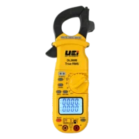
A digital multimeter with AC voltage, resistance (Ω), continuity, and capacitance (µF) capabilities covers everything you need here.
This step requires live voltage. Only proceed if you’re qualified to work with energized circuits.
Restore power and call for cooling. Set the multimeter to VAC. At the contactor, measure across the load side terminals. You should read approximately 240V. A 0V reading points to a bad contactor or upstream power problem, not the motor. If you read 240V and the fan isn’t moving, kill power, discharge the cap again, and continue.
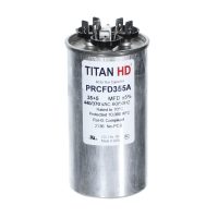
Disconnect the capacitor wires (photograph the connections first). Set the multimeter to capacitance (µF). Probe the C and FAN terminals.
Your reading should be within ±6% of the nameplate capacitor rating. For a 5 MFD cap, anything between 4.7 and 5.3 MFD is acceptable. Significantly lower or an OL reading means the capacitor has failed, replace it. If the cap tests good, move on to the motor windings.
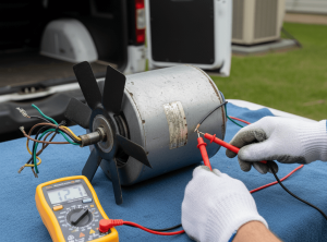
Unplug the motor leads from the panel. Set the multimeter to resistance (Ω) and test across all three wire pairs:
An OL (Open Line) reading across any pair means that winding is severed. Motor is dead, replace it.
If you have continuity, verify the resistance math: Common-to-Run + Common-to-Start should equal Start-to-Run. If your readings are 20Ω and 40Ω respectively, Start-to-Run must read 60Ω. A reading of 30Ω instead of 60Ω means the windings are shorting internally. Same result, motor is done.
Set the multimeter to its highest Ohms setting. Place one probe on bare metal on the motor casing (scratch through rust or paint to get clean contact). Touch the other probe to the Common, Run, and Start wires one at a time.
Every reading should be OL. Any resistance value, even a fluctuating one, means current is bleeding into the motor chassis. That’s a short to ground. The motor is permanently failed and will trip your breaker every time.
")
| Symptom | Diagnosis | Action |
|---|---|---|
| Blade won't spin manually | Seized bearings | Replace motor |
| Capacitor reads low or OL | Failed run capacitor | Replace capacitor |
| Motor winding reads OL | Open/broken winding | Replace motor |
| Resistance math doesn't add up | Internal winding short | Replace motor |
| Any resistance reading to chassis | Short to ground | Replace motor |
When ordering a replacement motor, match RPM and voltage exactly. You can upsize horsepower slightly if needed, but never downsize. And always swap in a new capacitor at the same time, running a new motor on an old capacitor puts your warranty and the motor at risk from the first hour of operation.
Running through this sequence (mechanical inspection, capacitor test, winding resistance, short-to-ground check) takes 20–30 minutes and eliminates guesswork. You’ll know exactly what failed and why before you order a single part. That means one trip, clean documentation, and a system that stays running.
For replacement motors, capacitors, and diagnostic tools, Jackson Systems stocks the components you need.
© Copyright 2026. All Rights Reserved.